Basic Tube cut-to-length methods
by William Holyoak, T-DRILL Industries Inc.
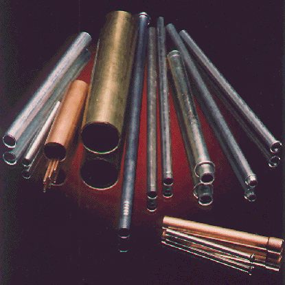
Cutting tubes to length is a basic industry requirement needed to provide a tube blank needed for further processing into a finished component through bending, end forming and/or further fabrication processes. While there are a wide variety of cutting processes, no singular method can cut the broad range of tubular materials and shapes produced by industry.
The factors used in deciding which method, and machine type, to use is determined by evaluating the following requirements:
- Production rates required to meet needs.
- End condition requirement.
- Tube material
- Production range of diameters and cut lengths
- Is the material supplied in coils or straight lengths?
The viability of each process will reflect the user needs, reflecting the inherent advantages and disadvantages for each of the situations.
SAW CUTTING
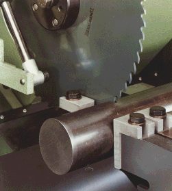
Sawing is one of the most versatile methods for re-cutting, utilizing a rotary (cold saw), or band saw to achieve the desired cut. It is a simple process, and can be adapted to a wide range cutting systems from a simple "chop" saw, to a sophisticated multi-head system based on the desired production level
| |
Figure 1. Typical chop saw
|
|
| |
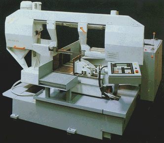
Figure 2. Typical band saw
|
|
| |
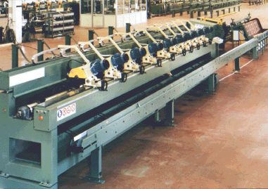
Figure 3. Multiple head saw
|
|
Cold saw characteristic
|
1. Tool Shape
|
|
|
2. Rake Angle
|
Positive 10ş to 20ş
|
|
3. Blade Materials
|
High Speed Steels (mainly M2)
|
|
4. Hardness Range
|
60 – 65 HRC
|
|
5. Blade Type
|
Segmental or Solid HSS Hollow Ground
|
The number of teeth will vary depending on tube diameter. The objective is to have the maximum number of teeth in contact on the tube, achieving the optimum production rate, and to minimize the vibration in the cutting operation. Too many teeth in contact with the tube may cause the chips to clog the teeth, severely reducing the saw's effectiveness. When cutting medium to thick walled tube some means of chip breaking must be provided, this can be provided by incorporating specialized bevels into the tooth design. The rake angle will vary from 10ş - 20ş, with the rake decreasing as the material hardness increases.
The saw blades are primarily constructed of high-speed steel (M2) and are available with various coatings to increase its performance, based on the material being cut. It's important in all cases to keep the blade cool to maintain the hardness. This is done by flooding the work zone with a soluble oil emulsion, or synthetic oil, to cool the blade, and lubricate the face of the tooth.
The typical blade is .80" -.120" thick, however, some of the newer coated blades have been used on a blade thickness of .040"- .070" thick. In addition, some applications have successfully used carbide tipped blades to increase performance.
LATHE CUTTING
The lathe cutting principals are best referenced in one of the SME manuals on standard machining practices for lathe, since the principal is the same, applying it to hollow bar stock (tubing) instead of solid material. The typical set-up employs a standard turning lathe where the tube is fed through a chuck type clamping system. The tube is then rotated, and cross carriage mounted tools part the tube, and when required, provide other operations such as chamfering (OD and ID). As well as other end form configurations.
The second arrangement utilizes a stationary tube, and rotates up to four cutting tools around the tube to part the tube, and provide end-finishing operations to the ID and OD of the tube.
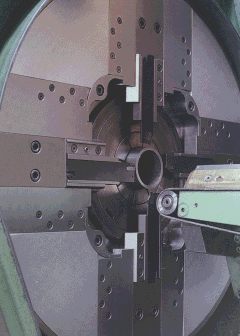
| |
Figure 4. Stationery tube with rotating cutting tools
|
|
The method is ideal for heavy wall tube, where the end configurations can only be achieved through a metal removal operation.
ROTARY CUTTING
Like many of the traditional cutting methods, rotary cutting as production system has been around since the early 1950's, utilizing a sophisticated version of the typical handtool used to part tubing. It incorporates one or more angled blades rotating around the tube to part the tube. Opposite each of the cutting blades is a backup roller to supply support for the parting process, and control the OD of the tube. Since material is displaced by the penetrating blade (instead of removed), the roller pressure redistributes the displaced material to maintain a constant O.D.

| |
Figure 5. Typical rotary cutting system
|
|
The cutting blades have an inclusive angle of 15ş to 40ş, dependent on the material thickness and hardness. The optimum situation is to use the minimum angle practical (i.e., 15ş), increasing it on harder materials to gain better tool life. The resultant cut will have ˝ the angle on the tube end face (7˝ş - 20ş), which is acceptable for most endforming operations. Special blade designs are available to achieve specific requirements, such as a flat end cut, or specific root radius.
On either side of the cutter, the tube is supported by clamps, while most machines have utilized standard ground and polished, vertical opening, clamps with the tube OD ground into them, recent developments provided for self centering, segmented clamps. The vertical clamps are subject to the variations in tube OD, and hence the tube centerline varies as the tube varies. The resultant cut is off center, and can effect cut quality. Using the self-centering (segmented) clamps assures that the centerline is maintained throughout the cutting process, providing the best possible quality.
The normal thru-cut provides some roll in of the material as the blade penetrates the tube (see Fig. 6) which is acceptable for most cutting applications where endforming is not a consideration. This can be improved on through a cut & break/cut & pull system (laterally moving the exit clamp), in which the tube is cut ~95% of the way through, then pulled or broken apart, providing minimum ID reduction suitable for end forming. The ID reduction will vary
depending on the material being cut, and the diameter.
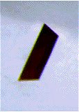
| |
Figure 6. Typical thru-cut
|
|
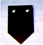
| |
Figure 7. Cut & pull/cut & break system
|
|
Through the use of extra back-up rolls, shapes can be imparted on the tube during the cutting operation to provide grooves, hose barbs and other shapes. This is done during the cutting cycle, and is limited to a maximum long approximately 1" longitudinally from the cut.
| |
Figure 8. Typical grooving operations.
|
|
The tube is supported on either side of the cutter
Since the cutting is chip-less, and in most cases ready for end forming, the modern rotary cut-off can be arranged with in-line end forming, to finish one end of the tube while the system has control of the tube. The in-line end forming is available with 1-4 punch forming stations, some with adjustable position to allow one of the punches to be end forming the part simultaneously with the cutting sequence. Consideration must be given to limiting the number of end forming operations to insure that the derived benefit is not offset by slower production speeds. See chapter 6 for end forming principles.
| |
Figure 9. Typical End forming operations
|
|
DUAL BLADE SHEAR CUTTING
The utilization of a blade shear to cut tubing has been used since the 1920's, starting with a single blade method, then improved on with the double blade system. Fig. 10 illustrates a typical dual blade system showing a horizontal blade removing a notch from the tube, followed by a vertical blade that shears the tube to length. Use of the initial scarf cut (horizontal) allows the vertical blade to penetrate the wall with minimum tube dimpling.
| |
Figure 10. Shear Cut
|
|
Because of the nature of the shearing process, the system is better suited for hard materials such as carbon and alloy steels. The resultant cut will have some burr and sharp edges, the magnitude of which is determined by the wall thickness and diameter of the tube. A brush de-burring system can be integrated to the equipment discharge to end finish both ends of the tube, ready for use in a system application.
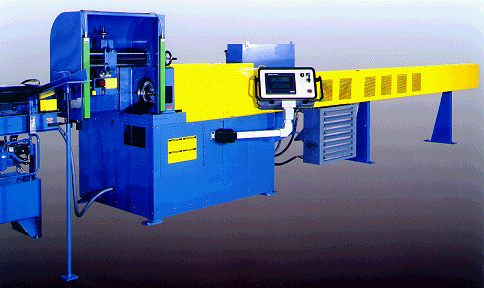
| |
Figure 11. Typical dual blade shear cutting machine.
|
|
The machine frame and shear drive components must be robust enough, usually cast, to provide the accuracy needed for the quality of the cut, and tool life, due to the forces involved in the shearing process. Like the rotary cutting process, the clamping quality and rigidity is essential to obtain the cut tolerances. The cutting tools are usually made from hardened M2 tool steel. The tools are often TIN coated for longer tool life. During the cutting process the horizontal blade cuts a small slug from the tube, which the vertical blade directs into the tube. The slug then folds under the vertical blade and is pushed through the bottom of the tube.
| |
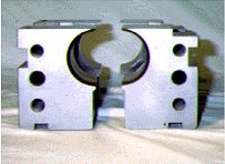
Figure 12. Supported Shear Tooling
|
|
SUPPORTED SHEAR CUTTING
The supported shear cutting system was developed in the 1950's to provide a burr-less cut on all types of metal tubes. In principal the cutting action is similar to a scissors, shearing the material between a fixed and moving blade.
Two tooling sections are utilized, one fixed (stationary), and one movable, consisting of an internal punch and an external die. The stationary tooling section supports the hollow tube interior with an internal punch, and supports the exterior with a close fitting external die. The movable tooling holds, moves and shears the desired segment of tubing (see Fig 13).
| |
Figure 13. Supported Shear Method
|
|
The sequence of operations starts when the mill length of tubing is loaded onto the machine through the external dies of both sections, and over both internal punches. A pusher advances the tubing to an adjustable stop finger, located behind the movable tooling. The stop finger is adjusted to the cut length.
When the tubing to be cut hits a stop mechanism, or a preprogrammed length, the shearing cycle begins. The movable tooling section will move against the stationary tooling section causing a shearing of the material. On some methods the movable section first moves vertically, and then horizontal. On other methods the movable section performs an elliptical loop to complete the cut.
At the end of the cutting cycle, the movable section returns to a fixed position, concentric with the stationary section, and the next tube to be cut is advanced. This ejects the cut segment, and the process is repeated. The cutting cycle is extremely fast, and the cut is made with not material loss between pieces
| |
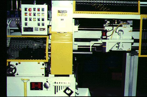
Figure 14. Typical Supported Shear Machine
|
|
LASER CUTTING
The use of lasers for cutting tube is in relative terms the most modern of technologies. It uses a power source to generate a beam of electromagnetic (EM) radiation to cut the tube. The beam has a specific wavelength, and those wavelengths are uniform, parallel and in phase with each other.
The two most popular laser systems for cutting tube are the CO2 and the Nd:YAG (Neodynium suspended in an yttrium garnet (YAG) crystal).
The principles of laser cutting, and the various methods used to generate the laser beam, are quite complex, and are covered in the applicable SME technical section.
The use of lasers in tube cutting has been most justifiable for parts requiring complex shapes, or a multitude of successive procedures, such as drilling punching, milling etc., which would require a series of different machines to complete the part. If the requirement is produce a finished product on demand, or produce small batches with a variety of modifications, laser cutting could be practical. Because of the inherent cost of a laser system, the justification must be based on the entire process, and maintenance costs must be considered.
| |
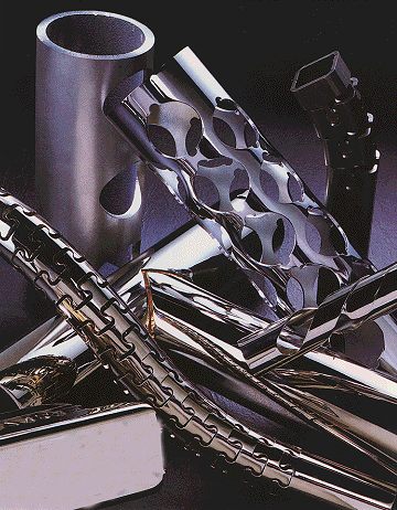
Figure 15. Laser Cut Parts
|
|
| |
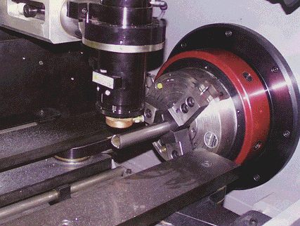
Figure 16. Typical Laser Applications
|
|
CAPABILITIES/LIMITATIONS OF CUT-TO-LENGTH PROCESSES
|
.
|
SAWING
|
LATHE CUT
|
SHEAR CUT
|
SUPPORTED SHEAR
|
ROTARY CUT
|
LASER CUT
|
|
COST
|
$
|
$$
|
$$$
|
$$$
|
$$
|
$$$$
|
|
SPEED
|
5
|
2
|
4
|
5*
|
2-4*
|
2
|
|
TUBE SHAPE
|
All
|
Round
|
Most
|
Most
|
Round
|
Complex
|
|
END CONDITION
|
Burr
|
Finished (if chamfered)
|
Burr
|
Burr-free
|
Slight taper
|
Finished (some hardening)
|
|
Size range
|
Unlimited
|
up to 8"
|
up to 5"
|
up to 4 1/2"
|
up to 3"
|
**
|
|
AUTOMATION
|
Machine
|
Machine
|
Machine
|
Machine
|
Workcell
|
Workcell
|
|
CONTAMINATION
|
Chips/lube
|
Chips/lube
|
Slug
|
None
|
None
|
None
|
|
MATERIAL LOSS
|
0.40" - 0.120" / cut
|
Significant
|
abt. 0.14" / cut
|
None
|
None
|
None
|
|
MATERIAL TYPE
|
All
|
All
|
Hard - limited soft
|
All
|
All
|
All
|
|
RAW MATERIAL FROM
|
Stick - limited coil
|
Stick
|
Stick - limited coil
|
Stick
|
Coil & Stick
|
Stick
|
$$$ = Relative equipment cost
1-5 = Relative production speed (max 6000 pcs / hour)
* High speed (6) on parts 1" or less in length, moderate (3) above 1" long
** Range based on type of equipment utilized
|
For further information please contact:
William Holyoak, President, T-DRILL Industries Inc.
- Addr: Norrcross, GA, USA
- Tel: (+1) 770-925-0520
- Fax: (+1) 770-925-3912
- WWW: http://www.t-drill.com
- Email.
|