New developments in tube pretreatment plants
By D.I. Fritz Nerat and
D.I. Jörg Papak
Körner Chemieanlagenbau GmbH
1. Introduction
Surface treatment of tubes is necessary for many products. The type of the pre-treatment
technology is different, depending on the different materials (carbon steel, stainless steel, non
ferrous, etc).
But there are many common aspects for the technical equipment, which is used for metal
pickling processes.
Due to the use of chemicals, which are more or less aggressive, the demands on the materials
applied in plant design are high. The resistance to chemical as well as mechanical attack
should be optimized.
In order to reduce operational cost it is necessary to minimize also maintenance cost.
Another important aspect of pretreatment lines is, to meet the requirements of environmental
regulations, which will become more strict in the future.
Following different solutions will be shown, how pre-treatment lines are executed today, in
order to meet the requirements of the market and the environmental regulations.
The new concept of encapsulated pre-treatment plants according the KVK-System from
Koerner KVK will also be introduced.
- Increasing productivity
- Improving quality
- Reducing personnel costs (through automation)
- Optimising materials use
- Increasing the service life of baths
- Reducing waste-disposal costs
- Reducing maintenance costs
Are the main targets for this system.
2. Different materials requires different pre-treatment
Following we will see an overview of different pre-treatment requirements, depending on the
materials and on final use of the tubes.
2.1. Galvanized tubes
These kind of plants need a special type of technical equipment ,especially for the galvanizing
process.
The pre-treatment of the tubes is done by degreasing (in most plants), pickling and fluxing.
The pickling chemicals, that are used are mainly HCl or H2SO4. In most of the plants the pre-treatment
line is a traditional open system, mostly without any, or with poor measures for
environmental protection.
2.2. Carbon tubes
Tubes, which are manufactured according DIN 2391 or DIN 2393 require chemical pre-treatment
prior to cold drawing. Pickling is only one step of the pre-treatment, which
normally consists of degreasing, pickling, phosphating soap. The pickling chemicals are
mainly H2SO4, but some plants use also HCl. Temperatures vary and depend on the pickling
chemicals (H2SO4 at approx 70°C and HCl between 30 and 50°C), but also on the special
know how of the companies.
Plants for these products are designed either traditional (without fume extraction) or with
lateral fume extraction on the pre-treatment tanks, which are operated at high temperatures
and/or with aggressive chemicals.
Only few plants are designed fully encapsulated (as for example Forster in Switzerland, or
TAP - tubos de acero de precision in Spain).
2.3. Stainless steel tubes
Pickling of stainless steel tubes requires very aggressive chemicals. A mixture of 2 or 3
componets acid is used in most of the companies. Pre-treatment plants for stainless steel are
equipped with fume extraction equipment as well as different types of purification systems.
In some plants the tanks are equipped with tanks covers in order to reduce the vapours. Also
pickling processes according the autoclave system are used in some companies.
2.4. Non ferrous metals
These kind of pickling lines are sometimes very special and consist of few tanks only.
The plants for Titanium tube pickling are similar to stainless steel pickling lines, whereas
pickling equipment for zirconium tubes is highly specialized and not used in other industries.
3. Types of pickling plants
In the description below focusses only on the technical key equipment of pre-treatment plants.
The main difference between the different types of plants is the way of reduction of vapours
and the way for fume purification.
Other external equipment which can be used in any type of plant (by pipe connection to the
tanks) like filters, deionisers, etc. are not considered here.
3.1. Standard type
This type of plant had been installed for decades and some of the plants are still in use without
big changes. The different pre-treatment tanks are standing in a building and are not equipped
with any fume extraction equipment.
The disadvantages for this type of plant are obvious. The vapours and aggressive fumes will
evaporate from the liquid surface and are distributed within the building. Steel structures,
electrical equipment, etc. will be attacked and destroyed, resulting in high maintenance costs.
3.2. Autoclave systems
The main target for optimising the pre-treatment section is to reduce the amount of vapours
and aggressive fumes, which cause destruction of equipment (cranes, building, stored
material, etc.).
One option, which is realized in some plants, is to use only one pre-treatment tank, where the
different processes (pickling, rinsing, etc.) are done by pumping the chemical from storage
tanks to the operating tank and vice versa.
These autoclave systems are equipped with covers for the tanks and with fume extraction
systems.
3.3. Plants with lateral fume extraction
The most common way for reduction of fumes and vapours is to install fume extraction
channels along the tanks. In principle there are two different types of fume extraction
systems- extraction on both lateral sides or a pushn pull system, where only the air is
extracted on one side and on the opposite side, there is a blowing pipe, which creates an air
curtain above the liquid surface. The latter method needs approx 20% less extraction volume.
If these systems are designed properly, they can catch most of the fumes while the material is
immersed or without material.
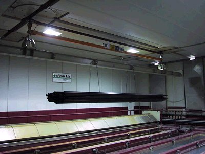
When the tube bundles are lifted after finishing the pickling process, a huge surface, which is
wetted with chemicals, is exposed to the atmosphere. In this position, no lateral fume
extraction system can catch the emissions coming from the tube bundle.
The surface of the tube bundles is more than twice as large as the liquid surface of the pre-treatment
tanks.
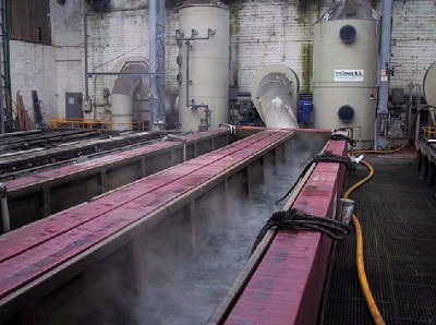
| |
Picture 1: pre-treatment tank with lateral fume extraction channels. Fumes are caught, when
tubes are immersed
|
|
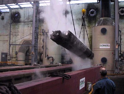
| |
Picture 2: aggressive fumes cannot be caught by lateral fume extraction channels, when tubes
are lifted
|
|
The required extraction volume is rather high and cannot avoid that aggressive fumes can
attack other equipment and the building.
For most pickling chemicals it is necessary to clean the extracted air. The size of the
purification systems (scrubbers in most cases) depends mainly on the volume of
decontaminated air.
3.4. KVK system, fully encapsulated pre-treatment
Encapsulated pre-treatment plants are a rather new technology for tube pickling plants. The
main advantages of this system are:
- no corrosion at the building and on equipment around the pre-treatment area. (cranes
etc.)
- space-saving (reduces building costs)
- high environmental standard
- low maintenance cost
- perfect working conditions for operators
- high quality
- highly economic
3.4.1. Basics of the KVK system
The KVK system will be described in a few words
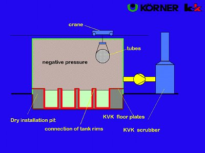
| |
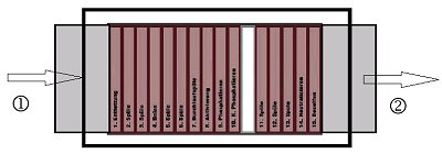
Picture 3.: Schematic illustration of the KVK-system
|
|
3.4.1.1.KVK tanks
The tanks used today are all free-standing and are installed in so-called installation pits
(concrete troughs) which collect the chemicals in the event of a tank leak (caused by
mechanical damage from falling parts) and prevent them escaping into the ground water.
The working tanks are sturdy KVK tanks, specially designed for the tough operating
conditions in pretreatment plants.
The tanks are placed close to eachother in order to minimize the required space for pickling
tanks.
It should be considered, that it is of big advantage, if the tanks can be repaired in the operating
position (that means without moving the tank) in case of damages.
The tanks can be equipped with additional parts, such as jig supports for exact positioning of
jigs on the tanks, or tube bundle separators.
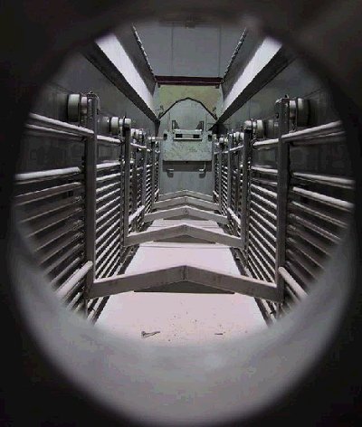
| |
Picture 4: Pickling tank with tube bundle separator and lateral heating elements
|
|
3.4.1.2. Enclosed pre-treatment
The greatest problem with respect to the generation of emissions is the "steaming off" of the
acid when the material is taken out of the bath. As mentioned above, this effect cannot be
solved by lateral fume extractions channels. The only way to solve this problem properly is to
encapsulate the whole pre-treatment area.
The Pre-treatment is enclosed using KVK panels. These panels are mounted on a steel or
wooden substructure and coated on the working side with glass-fibre reinforced plastic to
create a diffusion-tight, chemical-resistant shell isolated from the other production areas.
Since the cranes are running outside the encapsulated area, the ropes or chains enter the
encapsulated room through slots in the ceiling of the enclosure. These slots must be sealed
excellently in order to keep the fumes inside.
| |
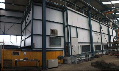
Picture 5: Encapsulated pickling area; only chains or ropes are exposed to aggressive air,
crane units are running outside
|
|
3.4.1.3. Dry installation pit
In the KVK System, the tanks are placed side-wall to side-wall, making optimum use of the
space available. The side-walls are glued together.
This also ensures that spilt chemicals cannot drip between the tank walls into the installation
pit.
The areas alongside the tanks are fitted with walkways made of acid-resistant, non-slip KVK
floor panels. The panels are mounted at the height of the upper edge of the tank and slope
inwards to the tank chamber. This ensures that any liquid drips will flow immediately back
into the correct tank, thus saving a considerable amount of chemicals.
This arrangement of maintenance access panels divides the pre-treatment unit into two
completely independent areas. The upper part (emission area, wet area) contains the
aggressive fumes resulting from the high solution temperatures. However, these fumes are
prevented from escaping from the enclosed pre-treatment unit and from entering the floor area
(cellar), since the KVK casing panels and the KVK maintenance access panels form a
diffusion-tight shell.
Since no chemicals or aggressive fumes enter the cellar part, the latter can be referred to as
dry installation pit.
This division of the pre-treatment unit into a wet emission area and a dry floor area can be
exploited in order to locate any sensitive parts requiring protection against corrosion at places
where they do not come into contact with the aggressive atmosphere. The dry cellar contains
all the automatic valves, pumps, electronic components such as transmitters, measuring
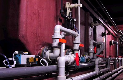
sensors etc. (see picture 6)
| |
Picture 6: Dry cellar; no agressive fumes attack the sensitive equipment |
|
3.4.1.4.Fume extraction system
The heating of the pickling liquid creates fumes in the emission area. However, these fumes
cannot escape thanks to the enclosed design of the pre-treatment unit.
It is absolutely necessary to create a negative pressure atmosphere inside the enclosure to
guarantee that no fumes will escape from the pickling area.
In the Koerner System, these fumes are continuously extracted through an extraction channel
and fed to a scrubber unit for purification.
The exhaust system is calculated specifically for each pre-treatment unit, since the complex
interplay of casing volume, air-lock gate opening, arrangement of exhaust air lines, and the
size and temperature of the bath surface make a simple design impossible.
A big difference between lateral extraction and extraction of encapsulated systems is, that the
volume to be extracted is much less in encapsulated system.
For a complete pre-treatment line one needs to extract approximately only that volume, that
would be necessary to extract two single tanks in open systems. This also the size of the
scrubber can be reduced.
3.4.2. Criteria in designing encapsulated pickling systems
The principle of the KVK system is very simple, but it might be very dangerous to install an
encapsulated pickling line without knowing the criteria in the design and calculation.
To design a modern system properly it was necessary to develop several calculation tools, that
cannot be purchased on the market. Special know how and the possibility to compare the
theoretical results with measurements in real plants, gave us the possibility, to adapt the
software modules. It is essential, to calculate the complex interactions in encapsulated plants
very closly to the real situation at the very beginning of the design of a project.
The main interfering aspects, that must be considered, are:
- Concentration of fumes inside the pickling area. This is necessary to design the
scrubber in the correct way. Several parameters are influencing this figure.
- To avoid fog inside the enclosure is essential. The climatic conditions need to be
considered very carefully, too.
- It must be guaranteed, that no fumes are escaping. The critical time is, when doors are
opened. Due to thermal gradients and inhomogeneous flow conditions inside the
enclosure, complex flow calculation programs are required.
Several patented inventions are incorporated in the design of modern encapsulated plants.
4. transport logistic
For the design of modern plants it is necessary not only to consider new technical and
technological aspects, but at least as important the optimum material logistic.
4.1. Analysis of the basic data
A profile on required standards as well as technological issues needs to be developed. It is
helpful, if the supplier of the chemical process is also involved in this discussion.
The planned quantities of material, procedural steps and timelines have to be described
systematically.
The next step is to analyze this fundamental data and integrate it into a new design. The first
step in this action plan is to prepare a grouping from the materials mixture of the product that
is to be produced, allowing the various products to be condensed into a similar sequence of
procedures. The outcome of these analyses are various process groups, for which the chemical
treatment operating sequence is similar.
The next step is to structure these procedural sequences for the respective material grouping
so that on the one hand an uniform direction in production without bottlenecks can be
guaranteed, and on the other hand, an optimum arrangement for incorporating automatic
transport systems can be found.
The result of these findings is the optimum configuration of process baths with respect to
(minimum )conversion times and (optimum) turn-around times.
Experiences were integrated along into this new design after visiting several facilities of
reference. The final and individually customized design is realized on the basis of these
findings and experiences from both, the supplier and the customer.
4.2. Material flow in encapsulated systems
In principle there are 2 different possibilities for encapsulated systems to enter and to leave
the pre-treatment area: crosswise or lengthwise.
4.2.1. Lengthwise logistic
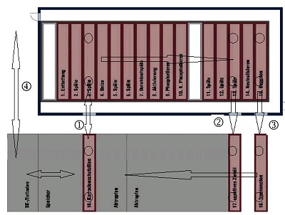
An example for material flow is outlined in a schematic drawing picture 7. Bundles of tubing
are transported by a conveyor system to the loading and drop-off stations. The bundles are
attached to carrier support beams secured with a harness strap. These carrier support beams sit
on specially prepared pick-up points and can be operated fully-automatically by the transport
system.
In principle, chemical pre-treatment is divided into two areas. Most of the processing baths
are located within the encapsulated pretreatment area which is fed through an access gate 1 or
through exit gates 1, 2, or 3. [picture 7.]
The second part of pretreatment essentially consists of oil baths, storage and dripping stations
and is set-up outside of the encapsulated system. A dryer is also located in this area.
It is possible to bring in the material either by shuttles or with monorails, where turntables
change the direction of transport.
| |
Picture 7: Length transport logistic
|
|
| |
Picture 8: Encapsulated plant with lateral material access.
|
|
4.2.2. Crosswise transportation logistic
In this system the tube bundles are taken over to hand over positions outside the pre-treatment
area. A hand over system (mainly chain conveyors) move the material into a position, where
the transport unit, that work for the pre-treatment, can take them over.
The transport units for the pre-treatment are running outside and are not exposed to aggressive
fumes at any time.
After the last step of pre-treatment, the material is handed over to the exit hand over unit, that
moves the material to the outside. (see principle in picture 9.)
| |
Picture 9: Principle of crosswise plant logistic
|
|
| |
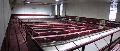
Picture 10: Crosswise plant in real operation.
|
|
4.2.3. Control system manual or automatic
Encapsulated pre-treatment lines can be operated manually, as well as automatically.
For automatic systems, the carrier support beams are transported from the loading and drop-off
points to the storage positions. The transport technology will then take them from there as
specified by the downstream processing control system and lead them through a sliding door
into the encapsulated pretreatment area.
Material identification as well as individual processing sequences are defined at the beginning
of the operational procedures and sent over to the respective transport unit via a process
control system. This process control system optimizes the operating sequence for the chemical
pre-treatment, in order to ensure optimum turn-around for various products as well.
Koerner KVK has developed a system, where standard overhead cranes can be used for the
encapsulated pre-treatment. For this new development it is possible, that the bridge cranes are
running outside the pre-treatment area and are never exposed to aggressive fumes.
If a plant should start with manual operation the savings for the initial investment can be
significantly, if the standard cranes can be unemployed used. This system enables the
customers to get full advantage of an encapsulated pre-treatment plant, while future
modification to an automatic system is possible.
5. Summary
The ever-increasing pressure of competition must be met by new ideas for system techniques
and technologies.
In order to reduce production costs, every stage in the production process must be optimised
and all system components optimally adjusted to each other.
There are many different options to reduce the problematic fumes in pre-treatment lines.
Since lateral fume extraction systems on pre-treatment tanks cannot avoid, that aggressive
fumes attack building and equipment, further fully encapsulated systems for the pre-treatment
plants seems to be the future design.
If the plant is designed based on specific know how, there are a lot of advantages compared to
other systems:
- By fully isolating the pre-treatment from other production areas, it is possible to operate
the baths at high temperatures without corrosion in the rest of the production area.
- Space-saving (reduces building costs)
- Enclosing the pre-treatment unit and extraction of the emission area (permanent partial
vacuum) provide the technical precondition for the use of modern automated transport
systems, thus increasing the degree of automation
- This systems can be operated manually or fully automatic, which reduces labour costs and
as far as possible eliminates the human factor as a source of errors.
- Enclosure prevents the escape of aggressive fumes from the pre-treatment unit, thus
preventing corrosion on crane equipment and building.
The design of encapsulated systems requires a lot of technological know how and special
knowledge in process engineering as well as thermodynamics and fluid dynamics.
The encapsulated pickling plant according the KVK-System is running in more than 20
plants all over the world.
For further information, please contact:
Koerner Chemieanlagenbau GmbH
- Attn: Fritz Nerat
- Tel: +43 3465 2513 18
- Fax: +43 3465 2118
- WWW: http://www.koerner.at
- Email.
| 

