Tube Bending Guide
by
Alex Slouka Jr, Omni-X
History
Rotary draw tube bending has come a long way since the days of crude manual tube bending machines bending tube with tools and dies made from wood. Technological advancements in machines, tools and materials have enabled many companies to switch from expensive welding of tubular assemblies to the more cost effective bending process.
In the past, the bending of tube on a centerline radius of less than 2D (2 times the diameter of the tube) was very difficult at best, and thus discouraged many companies from bending their tubes and opting for welding. With today's technology, 1D (1 times the diameter of the tube) bend are common, and even bends below 1D are possible. Another obstacle to bending was the inability to make the tooling that was capable of making compound and complex compound bends. With today's CNC machining capabilities and CAD/CAM technology, simple and complex compound tooling can be accurately manufactured at a cost which is no longer prohibitive.
The Basics
When a tube is bent, basically two things happen. The outside wall of the tube collapses and thins out, and the inside of the tube compresses and wrinkles.
The minimum tool requirements for rotary draw bending are the bend die (around which the tube is bent), clamp die (which holds the tube in place as it bends around the bend die), and the pressure die (which follows the tube as it bends around the bend die).
Satisfactory bends can be achieved using this minimal tooling when bending pipe, tubing with a heavy wall, or a large centerline radius. When bending light wall or thin wall tube the use of a mandrel and wiper die are necessary to make a nice bend. The mandrel minimizes the amount of collapse that will occur on the tube and the wiper die eliminates wrinkles on the inside radius of the tube.
It is important to keep in mind that the tooling is every bit as important as the actual bending machine. In most instances it is the tooling that will make or break a bend. Thus it is imperative to pay as much attention to detail when buying tooling as it is when buying a bending machine. Mixing and matching tooling or using inferior quality tooling will not pay off in the long run. Inferior tooling will wear out prematurely and may crack or break. Mixed and matched tooling also will not produce the quality bends that are expected from a set of tools built specifically as a set.
When buying tooling it is best to buy the bend die, clamp die, and pressure die at the same time to avoid any mismatching of the tube groove and insuring that the dies fit into each other properly. When tools don't match up properly your bends will not be consistent and damage to the outside of the tube will occur.
Another important aspect to making good bends is lubrication. Lubrication comes in several
different forms such as oil, grease and paste. The kind of lubrication used will depend on the material of the tube to be bent. A generous amount of lubrication may be applied to the mandrel and the inside of the tube, however precautions should be taken to avoid getting any lubrication on the bend die and clamp die. The amount applied will usually determine whether or not a good bend is made.
Components of rotary draw bending
The bend die is the primary tool which determines the bend radius of the tube. It is made from tool steel or alloy steel and is heat treated and /or nitrided depending on individual requirements.
Bend dies are available in several different styles. The five basic styles are shown below. The style chosen will depend on the tube outside diameter (O.D.) and the center line radius (CLR) of the bend as well as the configuration of the machine to be used. The five styles are:
1. Spool. 2. One piece 3. Partial platform 4. Full platform 5. Flange
|
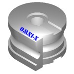
Spool |
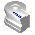
One Piece |
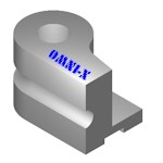
Partial Platform |
|
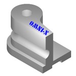
Full Platform |

Flange |
Bend die style animation
When choosing a bend die it is also important to consider whether the application will need precision tooling or commercial tooling. If you are bending standard to heavy walled pipe a standard, less costly set of tools will suffice. If on the other hand you are bending cosmetic or aerospace parts or thin walled tubing you may want to use a precision reverse interlock set of tools.
In addition to the different styles of bend dies, it is also important to choose the right grip length and grip surface of the die. The grip surface will depend on the application and is available with a sand blasted, carbide sprayed, knurled, or a serrated finish.
The clamp die is equal in length and has the same grip finish as the grip area of the bend die. The clamp die's primary function is to hold the tube securely to the bend die during bending.
The pressure die is used to maintain constant pressure on the tube at tangent where the bending is occurring, and thus provides the reactionary force to make the bend. The length of the pressure die depends on the degree of bend (DOB) of the part being bent.
The wiper die mounts into the tube groove of the bend die with the tip positioned near the tangent point. Its primary function is to prevent wrinkling on the inside radius of the tube.
The material the wiper die is made from is also important. Steel is
preferred for bending aluminum, copper, or mild steel; Aluminum-bronze for bending stainless steel, inconel, titanium. The steel wiper dies can also be hard chrome plated to help reduce friction.
Proper setup of the wiper die is essential to a good bend and the life of the die.
As with bend dies, there are several styles of wiper dies to choose from depending on
application:
-
Disposable inserts
-
Square back
-
Round back
Inserted wiper die |
Square back wiper die |
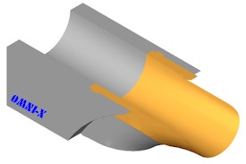
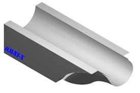
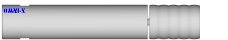
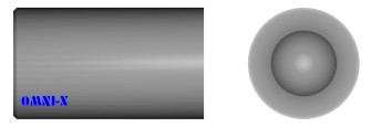
Mandrels are generally made from the same materials as the wiper die, usually steel with hard chrome plating or aluminum bronze, depending on the material being bent. The primary function of the mandrel is to prevent the outside diameter of the tube from collapsing.
Choosing the right mandrel is very important in determining the quality of the bend. There are five basic styles of mandrels to choose from.
They are:
- Plug mandrel - used for heavier walled tube or large CLR bending.
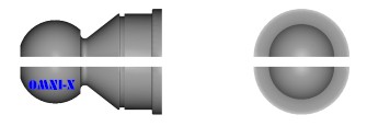
- Formed end plug - used for similar applications as plug mandrel but the formed end is machined to match
the CLR of the bend to provide more support on inside of the tube.
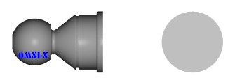
- Standard mandrel - most widely used because it covers the widest range of bending applications.
Standard mandrels are made with one ball or can be made with any amount of
balls. The standard mandrel is the most durable of the three flexible
mandrel configu- rations because it uses the largest size links possible.
- Thin wall mandrel (sometimes referred to as close pitch mandrel) - used mostly for thin wall
tubing (wall factor of 65 or more). Thin wall style mandrels use the same
style linkage as standard mandrels except the size of the link is the next
size smaller than it would be on a standard mandrel. For example, where a
standard style mandrel would use a #10 size link, a thin wall style mandrel
would use a #9 size link. The effect being that the ball segments are now
closer together and provide more support needed for thin walled tube
bending. Strength is sacrificed for more support.
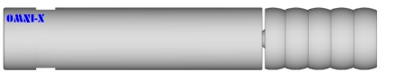
- Ultra thin wall mandrel - used with very thin wall tube. Ultra thin wall mandrels use the same style
links as the standard and thin wall mandrels but the size of the link is the
next size smaller than the thin wall size link or 2 sizes smaller than the
standard mandrel. So when we look at the example above where a standard
style mandrel uses a #10 size link, a thin wall style mandrel uses a #9 size
link, and a ultra-thin wall style mandrel uses a #8 size link. The effect
being that the ball segments are now closer together and provide more
support needed for thin walled tube bending. Strength is sacrificed for more
support.

Plug mandrel

Form end plug
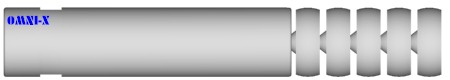
Standard mandrel
Thin wall mandrel
Ultra thin wall mandrel
Mandrel animation (Standard Mandrel)
Mandrel animation (Thin Wall Mandrel)
Mandrel animation (Ultra Thin Wall Mandrel)
Mandrel Assembly
Mandrel Assembly (Zoomed)
Mandrel Assembly (Zoomed more)
Mandrel link
Ball link
End link
Proper setup of rotary draw bending tools
When it comes to making the perfect bend on a consistent basis, several factors come into play, any one of which may make or break the bend.
The first step to take before making any bends is to determine that the bender you will be using is operating properly. Make sure that the clamping and unclamping of dies, the rotation of the swing arm, and the extracting of the mandrel, are all occurring in the proper sequence.
- Mandrel is located at tangent.
- Clamp die in.
- Pressure die in.
- Arm swings forward.
- Arm stops.
- Mandrel extracts.
- Clamp die and pressure die retract.
- Arm returns to zero position.
- Mandrel moves to forward position.
Once you are sure your machine is operating properly make sure that the tubes you will be bending are clean, both on the outside and the inside. Debris on the outside of the tubes will scratch and deface the grooves in the tools and will make the tools wear prematurely, especially the wiper die. Also, debris on the inside of the tubes will prematurely wear out the mandrel and may gall the inside of the tube.
Finally, check the tooling to make sure it is clean, burr free, and compatible with the tube to be bent.
After this preliminary inspection is completed you may proceed to setup the tools following these steps:
Bend die
Mount tools on the bending machine. Make sure the bend die is laying flat on the platform with the counterbore and key in place. Not hanging up. If there is debris under the bend die or it does not fit properly it will not bend properly.
Clamp die
Clamp the clamp die to the bend die. The grooves of the clamp die and the bend die should match up exactly. Adjust clamp die height as necessary. Also make sure the clamp die length is equal to the bend die length.
Pressure die
Mount the pressure die to the bending machine. The groove of the pressure die should match the groove of the bend die. Adjust the hangers as necessary. Be sure both the front and back of the pressure die are aligned with the bend die. Since the pressure die holds the tube against the bend die for the duration of the bend, make sure the pressure die is long enough to make the degree of bend you will be bending. Adjust the pressure die so that it applies medium pressure against the tube.
Wiper die
The next component to check is the wiper die. The tip of the wiper die should have a feather edge and the groove should match the groove of the bend die. The centerline radius should match the centerline radius of the bend die. When positioning the wiper die, do not go to or past the tangent of the bend die. The proper position for the wiper die is just behind the tangent. The best way to position the wiper die is to insert the tube over the mandrel and then clamp the clamp die to the bend die. Then advance the wiper die, by hand, as far forward in the bend die as it will go. Next, tap the back of the wiper die into the bend die until it cannot advance any further. The wiper die should now be in its proper position.
The wiper die material needs to be compatible with the tube material. A aluminum-bronze wiper die should be used when bending stainless steel, inconel, titanium, and other exotic materials. Use a steel wiper die when bending aluminum, steel, mild steel, and copper.
Mandrel
If using a mandrel, attach the mandrel to mandrel rod. Advance mandrel to the correct distance past the tangent point. Make sure that the mandrel is advancing and retracting in the proper sequence. The mandrel should advance to its preset position before the tube is inserted. After the bend is made the mandrel should retract. Further, make sure the mandrel is made from the a material that is best suited for the material you are bending. For example, a aluminum-bronze mandrel should be used when bending stainless steel, inconel, titanium and other exotic materials. A hard chrome plated steel mandrel should be used when bending aluminum, steel, mild steel, and copper. Do not forget to apply lubrication.
Trouble-shooting unsatisfactory bends
Tube breakage may be caused by the following:
- Material does not have the proper ductility and elongation properties.
- Tube slippage in the clamp die. Adjust pressure on the clamp die. Use different grip surface on the clamp die and grip section of bend die.
- Too much pressure on the pressure die causing excess drag. Reduce pressure on pressure die.
- Material is wrinkling and becoming locked between the mandrel balls. Use a thin wall style mandrel.
- Clamp die pressing on mandrel balls. Reduce pressure on clamp die.
- Not enough lubrication is being applied, or the wrong type of lubrication is being used.
- Mandrel is advanced too far forward past tangent. Move mandrel back.
Tube wrinkling may be caused by the following:
- Tube slippage in clamp die. Add pressure to clamp die or use a different grip in clamp die and the grip area of bend die.
- Mandrel is not far enough forward. Advance mandrel past tangent.
- Wiper die not in proper position. See appendix A.
- Wiper die is worn or not fitting properly. Make sure the centerline radius matches the centerline radius of bend die.
- Too much clearance between mandrel and tube. Try larger size mandrel.
- Not enough pressure on pressure die. Add pressure to pressure die.
- Excessive lubrication being used.
Commonly used tube bending terms
C.C.W.
Counter clock wise or left-hand rotation. On rotary draw tube bending machine the rotation of the arm swing.
C.W.
Clock wise or right-hand rotation. On rotary draw tube bending machine the rotation of the arm swing.
C.L.H.
Center line height. On a bending machine, the height from the bottom of bend die to the center of the tube groove on the die.
C.L.R.
Radius along the centerline of the tube to be bent. See appendix A.
Captive lip
Tooling in which the groove in the bend die and wiper die is deeper than half the diameter of the tube. Used only with interlock tools in high precision aerospace applications minimizes tool marks from the bend die in ultra thin wall applications.
Carbide coating
Surface treatment to bend die grip sections and clamp dies to help prevent tube slippage.
Compound tooling
Tooling that has very short DBB (distance between bends) requires that the bend die grip section and the clamp die have the previous bend machined into them. Tooling is expensive but more practical than short grip sections in high production applications.
D.O.B.
Degree of bend. Number of degrees a tube is to be bent.
"D" of bend
The centerline radius divided by tube O.D.
D.B.B.
Distance between bends. The distance between the tangent of one bend and the tangent of another bend.
E-plane
Refers to the direction of bend for rectangular tubes. The tube stands vertically when placed into the bend die.
Galling
The transference of one material to another caused by high pressure and friction. Occurs when stainless steel is bent with a steel mandrel or wiper die; or when aluminum is bent with aluminum-bronze tools. Can be reduced by using better lubricants, alternate materials, or a slow arm rotation may help.
H-plane
Refers to the direction of bend for rectangular tubes. The tube lays horizontally when placed in the bend die.
Integral grip
If a bend die has a removable grip section, it is the straight portion of the groove between the grip and the tangent point.
I.S.R.
Inside radius of bend. Typically used when specifying radius to bend on rectangular and square tubes. ISR = CLR minus half of O.D.
Knurl
Surface treatment to bend die grip section and clamp die to prevent slippage. Fine and coarse knurls are available. Does not deform or mark the tube the way serration does.
Mandrel extractor
The hydraulic cylinder that removes the mandrel from the tube after bending. Necessary only when mandrel is being used.
P.O.B.
Plane of bend. Refers to the amount of rotation between two bends. Specified in degrees.
Pressure die assist
A hydraulic cylinder attached to the pressure die master bar. It forces the pressure die to push the tube during bending. This action reduces collapse and wall thinning and improves ovality of the tube by forcing more material to the areas of the tube where it is stretching and thinning out during bending. Primarily used thin wall precision applications.
Radial growth
After a tube is bent, it will spring back and the radius of the tube will grow. It will be larger than the bend die CLR. Radial growth is greatest with CLRs greater than three times the tube O.D. and when bending harder materials.
Reverse interlock
Tooling that utilizes an interlocking design in which the wiper die, clamp die and the pressure die fit into the bend
die. Used primarily for cosmetic or aerospace parts and high production bending.
Serration
Surface treatment to bend die grip section and clamp die to prevent slippage. Usually used with grip section shorter than three times the tube O.D. Tube deformation and marks should be expected.
Springback
When a material is bent it has a tendency to want to return back to its original position. The amount that it does actually return is called springback. The springback amount will differ depending on the material being bent and the CLR on which it is bent.
Thin wall mandrel
Tube I.D.
Inside diameter of tube.
Tube O.D.
Outside diameter of tube.
Ultra thin wall mandrel
Wall factor
Tube O.D. divided by wall thickness.
Wall
Wall thickness or gauge of tube or pipe.
Further information can be obtained from:
OMNI-X, Inc.
- Attn: Alex Slouka Jr.
- Tel. 303-789-3575
- Fax. 303-789-4755
- WWW. http://www.omnibend.com/
- Email.
|