|
Performance Improvement of Rotary
Ultrasonic Testers
J Venczel, Magnetic Analysis Corp., USA
Abstract |
In Rotary Ultrasonic Testers the transducers rotate around the tube. The signal
connection to and from the transducers represents a critical part of the tester.
The task can be accomplished by one of three methods: slip rings, rotary
capacitors and rotary transformers. Naturally, each has advantages and
disadvantages. The paper analyzes these methods and offers an optimal solution.
Detailed description of a working Rotary Tester is given with test results in
tube and bar testing
Introduction
In order to insure a flawless product in the tube industry the final phase of
production must be the nondestructive inspection. Eddy current inspection is
capable of detecting surface flaws on the outside surface of the tubes but not
on the inside surface or deep in the wall of the tube. Ultrasonic inspection can
find flaws both on outside and inside surfaces, usually referred to as OD and
ID, as well as internal flaws. Utilizing the circular symmetry of tubes, it is
possible to achive100% inspection by rotating the tube in front of the
transducer or rotating the transducer around the tube. Rotating a tube at 3000
to 4000 RPM is difficult to achieve, therefore rotating the transducer allows a
higher inspection speed. Transducer rotation makes it more difficult to connect
electrical signals to and from the transducer. There are three main methods for
coupling electrical signals to rotating parts: slip rings, rotary capacitors,
and rotary transformers. The main problem with slip rings is the electrical
noise they generate; also, at high speed, it is difficult to maintain reliable
electrical conductivity between the slip ring and the brush. Rotary capacitors
are better with respect to noise but more difficult to make. Ultrasonic signals
in case of nondestructive testing are in the frequency band of 0.5 MHz to about
20 MHz, or higher. To pass such a wideband signal, the coupling capacitors have
to be in the range of 500 to 2000 pF for each channel. To realize this kind of
capacitance the capacitor plates have to be placed close to each other and have
a large surface. This, in turn, requires careful design and precision machining
operation. The parasitic capacitance between plate and ground leads to loss of
signal, while the mutual capacitance between plates of adjacent channels results
in crosstalk between channels. Rotary transformers made of high frequency
ferrite material are capable of handling the required high frequency signals but
have problems transmitting the high voltage initial pulse, which may be 500 to
600 volt. Until recently, rotary capacitors were used predominantly in rotary
testers. The application of rotary transformers is new but it has several
advantages which will be discussed in the following.
Rotary capacitors vs. rotary transformers
A rotary tester requires several channels for a typical application. Four
channels are required for a clockwise, counterclockwise, forward, and reverse
shear wave testing and a fifth channel for wall thickness measurement. Higher
inspection speed requirement leads to more channels. Testers often have seven or
twelve channels for increased inspection speed. Failure of rotary testers is
often caused by dirt or water in the rotary capacitors. Crosstalk between
channels is a serious problem and it gets worse with increased number of
channels. The coupling loss through capacitors is typically 7 to 10 dB and the
signal path includes the ground connection between the rotor and the stator.
Figure 1 shows the electrical connection between a pulser receiver and a rotary
tester when using a rotary capacitor. The rotary capacitor has parasitic
components on input to stator ground and on the output to rotor ground. These
capacitances have a shunting effect, which decreases signal strength both in
connecting the initial pulse to the transducer on the rotor and connecting the
received echo signals to the pulser-receiver. The return path of electrical
connection is accomplished through the ground connection between the stator and
rotor. A conductive seal or a slip ring is used to make the electrical
connection between the bodies of stator and rotor but it also acts as a noise
source added to the input signal of the pulser-receiver. The application of a
rotary transformer is shown on Figure 2. The coupling ratio is usually
one-to-one but other ratios are also possible for better impedance matching. The
effect of
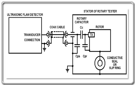 | |
Figure 1.
|
|
parasitic capacitances is minimal and so is the crosstalk
between channels. The use of a conductive seal or slip ring type of ground
connection is still required but it is no longer part of the signal return. The
main problem, however, is that the ferrite transformers can not efficiently
transmit the high voltage initial pulse. To overcome this problem a remote pulse
preamplifier Was used. This, in turn, created a new problem by requiring
electrical power Conducted to the rotor. This was accomplished by adding a power
transformer to the set of signal transformers and a power supply board with
rectifier and DC-to-DC converters. The end result was an ultrasonic rotary
tester with rotor mounted electronic processing circuits.
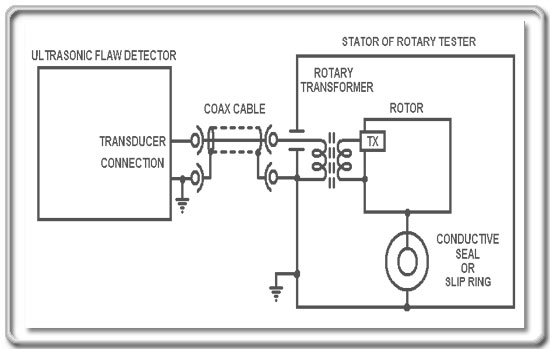 | |
Figure 2.
|
|
Rotary ultrasonic tester with on-board electronics
The example for this product is a seven-channel rotary tester. Three of the
channels are set up to operate in compression mode for longitudinal wave testing
and four to operate in shear wave mode. The pulser of the ultrasonic flaw
detector is set up to operate with a reduced amplitude initial pulse, since it
functions only as a synchronizing signal for the pulser circuit on the rotor.
Each channel of the flaw detector is connected to the rotary by a single cable.
This cable has to conduct signals in both directions. The approximately 10V
amplitude initial pulse is generated in the flaw detector and connects to the
rotor- mounted pulser via the
rotary transformer. The 500V amplitude output of the pulser is connected to the
transducer. The echo signals received by the transducer are connected to the
input of the preamplifier in the pulse-echo arrangement. You can set the gain of
the preamplifier in four steps by slide switches on the PC board individually
for each channel. For best signal-to-noise ratio the gain of the preamplifier
has to be as high as possible without saturation. On the other hand, in some
applications the signals are very strong and the amplifier gain has to be
reduced to prevent saturation.
The slide switches allow a coarse setting of the gain in 6 dB steps. The output
impedance of the preamplifier is 50 ohm to match the characteristic impedance of
the interconnecting
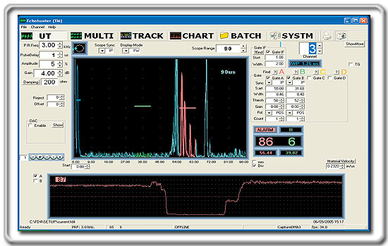 | |
Figure 3.
|
|
cable. To be able to use a single cable to conduct signals in
both directions, we use a technique that is called “amplitude division
multiplexing”. The amplitude range of +/-5 volts is assigned to the preamplified
echo signals from the rotor to the flaw detector. The -5 to -10 volts range is
assigned to the transmission of synchronizing initial pulse from the flaw
detector to the pulser on the rotor. In evaluations the signal to noise ratio
was found to be about 10dB better compared to the traditional rotary tester.
Figure 3 shows the setup screen of the ultrasonic tester detecting a 0.3 mm deep
and 0.3 mm wide surface notch. The bottom of the screen shows the strip chart
recording of a calibration standard with signal amplitudes on and off the notch.
On the A-scan presentation, the signal amplitude is 86% under the red gate while
the noise level is 6% under the green gate. Ground loop noise is practically
eliminated because of transformer coupling. It is hard to measure numerical
improvement in resistance to electromagnetic interference, EMI, but it appeared
to be less. Crosstalk between channels is so low that it is not a problem any
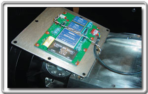
longer. The most difficult problem we faced during the design was to mount the
circuit boards in such a way that they can withstand the centrifugal forces
during operation. Figures 4, 5, 6 and 7 show the mounting arrangement of the
rotor-mounted printed circuit boards.
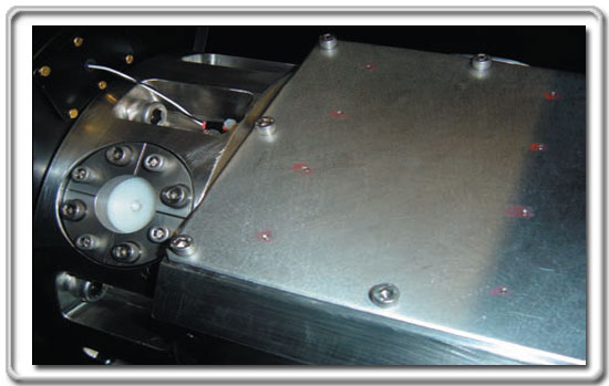 | |
Figure 4
|
|
 |
| |
Figure 5 |
|
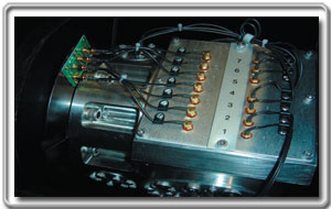 | |
Figure 6 |
|
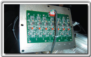 | |
Figure 7 |
|
Conclusions
In the last few years, the rotary testers are facing a serious competition from
phased array systems. Phased arrays offer many advantages. First of all there
are no moving parts, the scanning is done electronically. Phased array systems
also offer a number of advanced features, like variable focal length, electronic
switching between compression and shear wave modes and possibly others, but many
applications do not require those. The major disadvantage of a phased array
system is the cost, which is much higher then that of a rotary tester. In multi
channel applications the rotary testers offer a lower cost alternative to phased
arrays and the addition of on board electronics improves the ability to find
small defects reliably at high inspection speed. Plans for new developments
include the addition of remote control for the rotary mounted pulser-preamplifier.
Remote control of pulse amplitude, amplifier gain and damping can add
flexibility to setup and operation. RF data links of 900 MHz or other frequency
are quite suitable for application in rotary testers.
Contact Person:
John Venczel
Engineering Manager
Ultrasonic Development
Magnetic Analysis Corporation
Phone: (914)699-9450
Fax: (914)699-9837
Email:
|